DFM Review for Silicone Parts: Ten Checks Before You Cut Steel
Read:8
Most silicone cost problems are locked in before the mould is cut, and a two-hour design-for-manufacture review is the cheapest stage of any project. The conclusion for buyers: run the ten checks below against your drawing before releasing tooling, because every one of them is inexpensive to change on a screen and expensive to change in steel — and several cannot be changed at all once the tool exists.
The ten checks, in the order they cause trouble
1. Wall thickness uniformity
Silicone shrinks as it cures, and thick sections shrink more than thin ones. A part with a 6 mm boss next to a 1.5 mm wall will sink, distort, or develop internal voids, and no amount of press tuning fixes it. Aim for uniform walls, and where a thick section is functionally necessary, core it out from the non-cosmetic side or thin it with a recess. As an orientation, walls below about 0.8 mm are difficult in compression moulding and become a liquid-silicone design.
2. Draft on every vertical face
Soft material does not mean the part releases itself. Silicone grips polished steel, and a zero-draft wall will drag, tear at the parting line, or need manual assistance on every cycle. One to two degrees is normal for textured surfaces, half a degree can work on smooth walls, and deeper cavities need more. Draft is nearly free to add at design stage and awkward to add later, because it changes the nominal dimension your other parts mate with.
3. Radii instead of sharp internal corners
Sharp inside corners concentrate stress and are the first place a part tears during demoulding or in service. A minimum internal radius of about 0.5 mm, and ideally 1 mm or more on load-bearing corners, removes the stress riser. On the outside, a small radius also prevents the feather edge that makes flash trimming unreliable.
4. Undercuts: count them, then decide
Every undercut needs either a split line, a collapsing core, a pick-out by hand, or a material that stretches enough to release. One shallow undercut on a soft 40 Shore A part is often acceptable; three undercuts on a 70 Shore A part usually force a more expensive tool. List them on the drawing, because suppliers price what they see and later discover what they missed.
5. Parting line placement
The parting line is visible, and it is also where flash forms. Put it where a consumer will not look, or where a texture will disguise it, and specify it on the drawing. If the parting line falls across a sealing surface or a printed area, either move it or budget for post-processing. This single decision drives both appearance and unit cost.
6. Tolerance stack against function
Dimensional tolerances on silicone are wider than on machined plastic, and ISO 3302-1 grades them by size. Mark which dimensions are functional and which are reference. A drawing with ±0.1 mm on every dimension will be quoted high, inspected heavily, and rejected often — for no functional reason.
7. Gate and vent positions
Where material enters leaves a mark, and where air cannot escape leaves a bubble or a burn. For visible parts, put the gate on a hidden face and discuss venting at the review rather than after the first sample. On large flat parts, venting is the difference between a 2% and a 10% scrap rate.
8. Inserts and overmoulding
If the part carries a metal insert, a magnet, or bonds to plastic, the review must cover how it is located during cure, what happens to the silicone around it, and whether the insert can be replaced if it fails. Inserts moulded blind into a thick section are a common source of post-cure pull-out failures.
9. Surface, colour and decoration zones
Printing, laser marking and spray coating all need a flat or gently curved, well-defined area, and they add process steps that must be sequenced after cure. Mark decoration zones and their boundaries on the drawing. A logo that wraps a tight radius will print unevenly no matter how good the pad printer is.
10. Packing and handling
Soft parts deform in bulk. A design with thin protruding features will arrive bent, and a part that nests tightly will slow your line. Ask how the part will be packed — bulk bag, tray, or individual bag — and whether the packing protects the features that matter. This is a design decision as much as a logistics one.
The review output you should expect
| Design feature | Risk if ignored | Typical fix | Cost impact of fixing late |
|---|---|---|---|
| Thick-to-thin wall transition | Sink marks, voids, distortion | Core out or step the transition | Tool re-cut, possibly new tool |
| Zero draft | Tearing, manual demoulding, slow cycle | Add 1–2° draft | Tool re-cut plus sample re-approval |
| Sharp internal corner | Tear initiation, field failures | Add 0.5–1 mm radius | Tool polish; may need new insert |
| Multiple undercuts | Complex tooling, high unit price | Redesign to one split or a snap feature | New tool |
| Parting line on seal face | Leak paths, flash on function | Relocate parting line | New tool |
| Blanket tight tolerances | High price, high reject rate | Tolerance only functional dimensions | Renegotiation, inspection cost |
| Gate on visible face | Cosmetic reject | Move gate, add a disguise feature | Tool modification |
| Unprotected protruding features | Deformation in transit | Tray packing or design change | Packaging cost forever |
How to run the review efficiently
- Send the 3D file plus a drawing with tolerances, material, colour and finish.
- Ask for written comments, not a verbal "it is fine" — a marked-up drawing is auditable.
- Ask specifically which features the supplier would change if the tool were theirs.
- Resolve open points before the tool is cut; after that, changes cost steel.
- Keep the review record with the approved sample, so a later change can be traced to who approved it.
FAQ
Can a supplier do a DFM review without a 3D file?
Only superficially. A 2D drawing shows nominal dimensions but not the transitions that cause shrinkage and venting problems. If you only have a drawing, expect a conditional review and more conservative tolerances.
Does DFM review delay the project?
It typically takes a few days and usually saves more than it costs, because every issue found on screen avoids a tool modification and a re-sampling round of two to four weeks.
Who owns the DFM comments?
The comments are advice, the drawing is your specification. Anything you accept becomes a requirement; anything you decline should be recorded, because it shifts the risk of that feature back to you.
Is a DFM review necessary for a simple part?
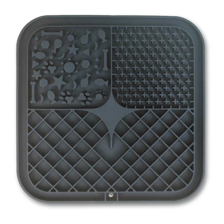
Yes, but it can be short. Even a flat mat benefits from a parting-line and venting discussion, and those two items decide the scrap rate for the life of the tool.
Next step
Send your drawing and we will return a marked-up DFM review with the specific changes we would make before cutting steel. See how the process works on our custom silicone OEM and ODM service page, with reference parts in silicone baby products and silicone travel bottles.