Silicone Dimensional Tolerances: What ISO 3302 Allows and What Your Drawing Should Say
Read:9
Most disputes about silicone part dimensions start with a drawing copied from a plastic part. Silicone shrinks, deforms on demoulding and deflects under measurement force, so it cannot hold ±0.05 mm on a free surface. The workable approach: use ISO 3302 tolerance classes as the default, tighten only the two or three dimensions that are functionally critical, and agree the measurement method in writing. This article shows what the standard allows and how to apply it.
Why silicone behaves differently from rigid plastics
Three physical effects set the limits. First, moulded shrinkage of 2–3.5% varies with hardness, pigment loading and cure conditions, so the tool is cut to a predicted shrinkage and corrected after T1 trials. Second, a soft elastomer releases from the mould by stretching, which shifts thin features and undercuts slightly every cycle. Third, a durometer or caliper jaw compresses the surface by an amount that depends on operator force — a 40 Shore A wall measured "hard" by two inspectors can differ by tenths of a millimetre without either being wrong.
The consequence is that a tolerance is only meaningful when paired with a measurement method: contact or optical, on which surface, with what conditioning. Professionals specify both together.
What ISO 3302 actually permits
ISO 3302-1 defines tolerance classes for rubber parts; silicone moulders most often quote M2 (tighter) or M3 (general) for dimension A (fixed dimensions across the parting line) and dimensions C (overall) and W (wall thickness). The table shows indicative values for typical consumer-part sizes:
| Nominal size | Class M2 (tight) | Class M3 (general) | Practical use |
|---|---|---|---|
| Up to 10 mm | ±0.20 mm | ±0.35 mm | Small caps, seals, small charms |
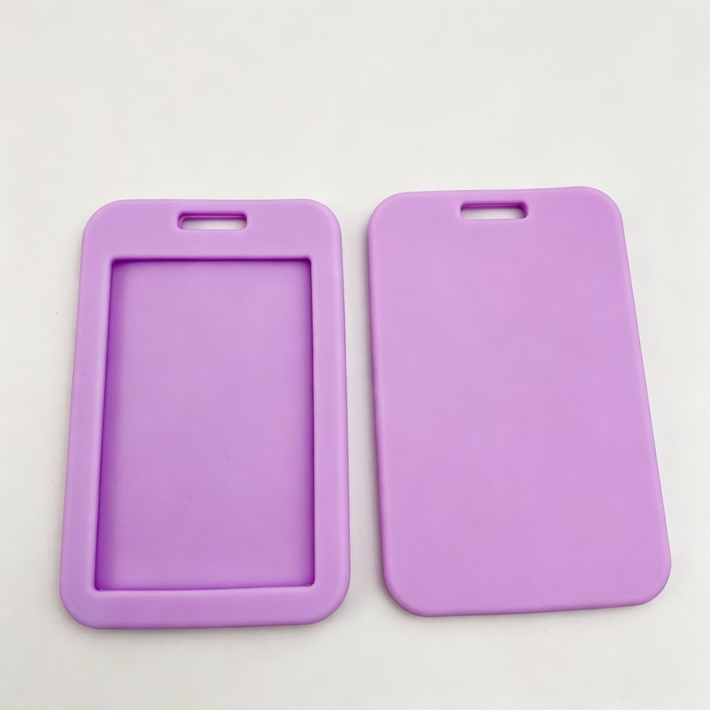
| 10–40 mm | ±0.35 mm | ±0.50 mm | Phone cases, utensil heads, bottle bodies |
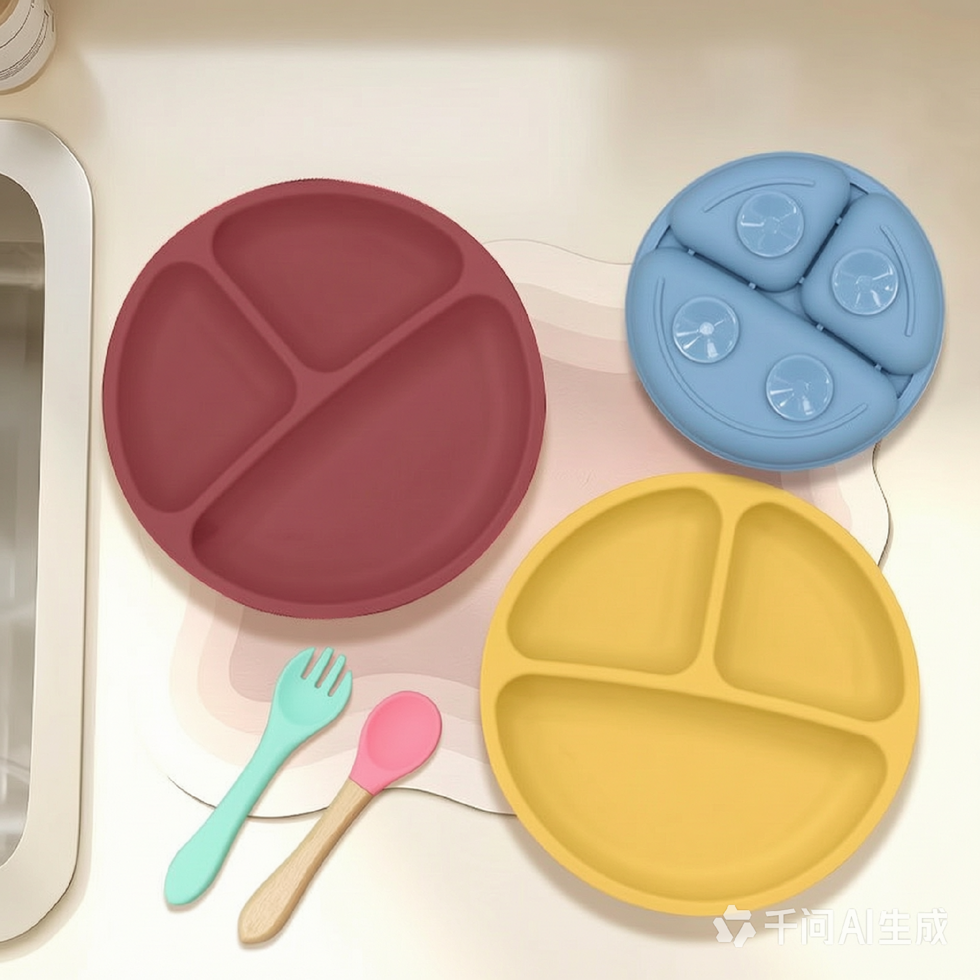
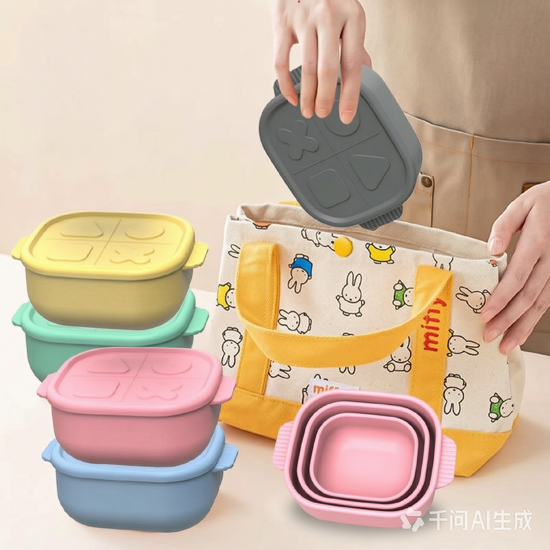
| 40–100 mm | ±0.45 mm | ±0.80 mm | Bowls, plates, collapsible bottles |
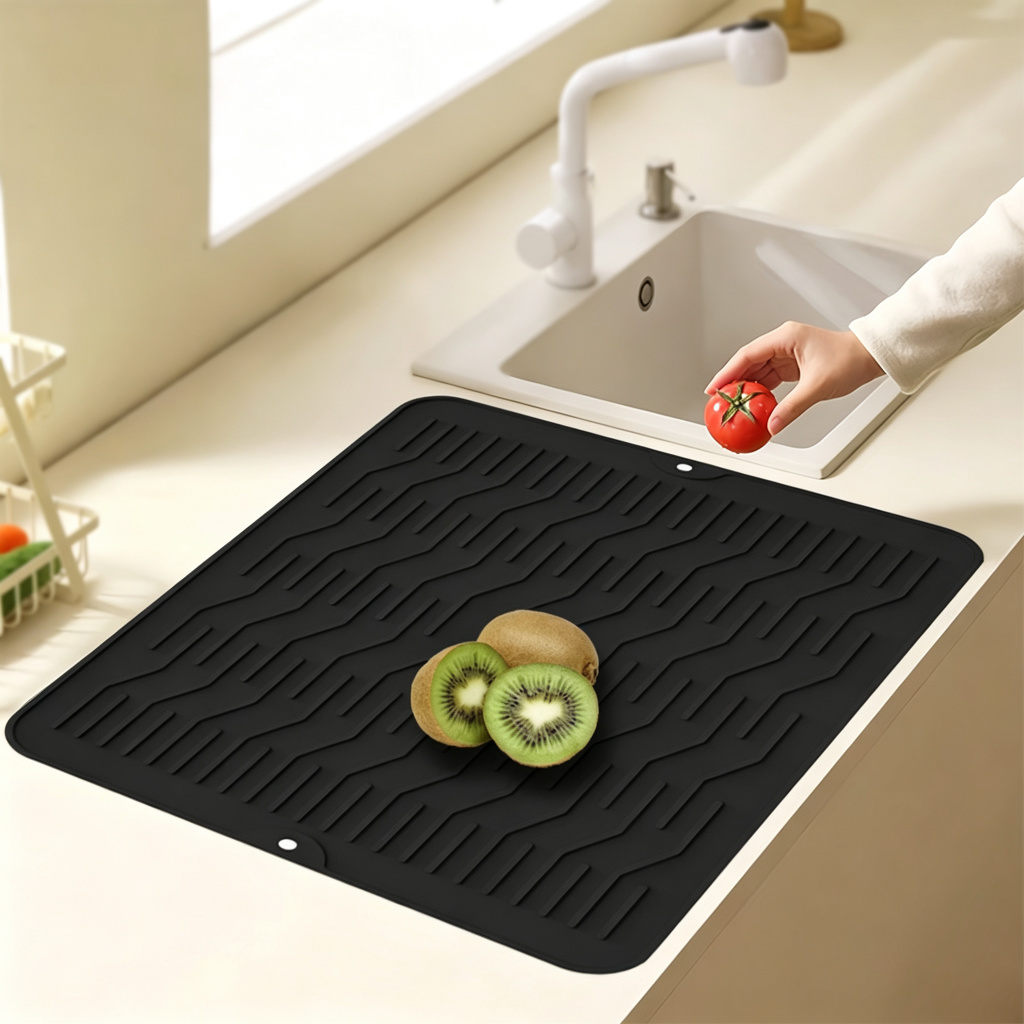
| 100–160 mm | ±0.60 mm | ±1.00 mm | Large mats, trays, pet feeders |
| 160–400 mm | ±1.00 mm | ±1.50 mm | Oversized mats, integrated items |
These are achievable production tolerances, not sample tolerances. A factory promising M2 values on every dimension is either planning to reject parts you would accept, or has not understood the request — both predict trouble.
How to mark tolerances on your drawing
- Default to a class, not a list. State "ISO 3302-1 class M3 unless otherwise noted" in the title block. This covers the dozens of non-critical dimensions without negotiation.
- Tighten only functional dimensions. A sealing diameter, a mating depth, a button travel distance — typically two to four features — get explicit, tighter values and class M2 where justified.
- Distinguish fixed from free dimensions. Features formed by both mould halves (across the parting line) are inherently less stable than features formed in one half; do not assign the same tolerance to both.
- Give datum points. Measure from a defined datum, not "overall length somewhere", so inspection reports are comparable.
- State the measurement method for critical dimensions: "optical profile, non-contact" for thin walls; "caliper, 0.5 N jaw force, after 24 h conditioning" where contact is acceptable.
Shrinkage, tooling correction and the T1 cycle
The first sample round exists to converge dimensions. Expect this sequence on a new tool: T1 samples measured on the critical dimensions; a shrinkage comparison against target; one tool correction (typically steel-safe adjustments, occasionally adding metal); then T2 approval. Build one correction cycle into your schedule and your tooling budget — a project promised "no corrections" is a project that will skip measurement and surprise you later.
Hardness interacts here: below about 35 Shore A, expect to relax non-critical tolerances one class or redesign toward more generous radii. Above about 60 Shore A, dimensions hold better but demoulding stress rises, which shows up as flash variation instead.
What inspection should look like
A credible dimensional report for a silicone part includes: the dimension with its nominal and tolerance, the measured value on each of three sampled parts, the instrument used, and a pass/fail against the drawing class. Reports showing a single number with no reference to tolerance are decorative. During first-article inspection, measure the part after 24 hours at room temperature — silicone dimensions creep back after demoulding, and measuring hot parts off the press gives optimistic errors.
FAQ
Can silicone hold ±0.05 mm anywhere?
Only on hard-tool-formed features in high-hardness compounds, and rarely across the parting line. If a mating requirement truly needs plastic-level precision, the usual answer is a silicone-over-hard-part construction, where the rigid carrier holds the tolerance.
Why did my second batch measure slightly larger?
Most often a different post-cure or a corrected tool set to the first batch's shrinkage measurement — both legitimate. The fix is procedural: record the tool correction and re-baseline the inspection report after any correction cycle.
Does colour affect tolerance?
High pigment loading shifts shrinkage slightly, which is why tight-tolerance parts should be sampled in the production colour, not in natural translucent material.
What tolerance should a phone case quote use?
Class M3 on free surfaces with M2 on the corner radius and any camera-opening features is a common, buildable starting point. See our OEM and ODM service for how we review drawings, or browse product categories for reference parts.
Next step
Send us your drawing and we will return it with a proposed tolerance class, the dimensions we would tighten and those we would relax — before you commit tooling money. Start at our custom silicone OEM and ODM service page.